|
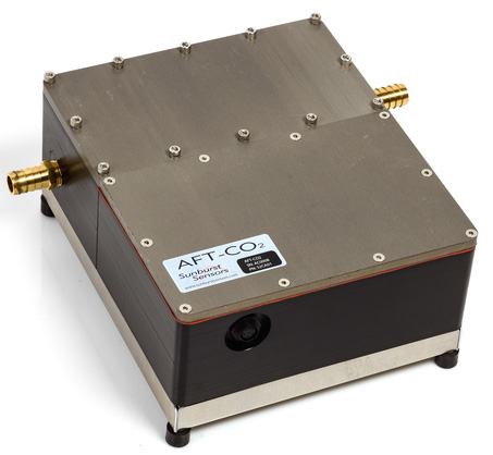
General Description: The Sami pCO2 analyzer utilizes a gas permeable membrane, which permits CO2 from seawater to diffuse to an indicator solution. The CO2 combines with water in the solution to form bicarbonate and carbonate, thus decreasing the pH of the indicator solution. Once the indicator solution has equilibrated with the seawater (ca. 5 min.), the pH of the solution is read using a spectrophotometer using three frequencies (2 frequencies for the pH (620 nm and 434 nm), 1 frequency as a blank to test for solution degradation and drift (740 nm?)). (Degrandpre et al 2000, see Wanninkhof et al 2013) Accuracy: ±3 µatm (Sunburst website) Precision: <1 µatm (Sunburst website) Drift: <1 µatm over 6 months (Sunburst website) Equilibration Method: Gas permeable membrane allows CO2 to equilibrate with an indicator solution, changing the pH of the solution. Sensor: Spectrophotometric using 3 wavelengths. Can support external instruments. Notes: Limited to surface waters in its underway form (see Sunburst SAMI for in-situ measurements). Reagents must be replaced (ca. 7500 measurements per 1 reagent bag). Must be sent in for calibration (supposedly?). Does not measure atmospheric pCO2. Calibrations: Must be sent in for calibration (how often?). May be able to calibrate against bottle samples. Portability: Low. Ship-board, but does not require standard gases as the GO system does. Installation and Spatial requirements: AFT-CO2 housing (25.4x30.5x14 cm, 7 kg). Requires access to surface seawater and the intake must be sufficiently distant from any pollutants, such as a ship’s waste water outlet. Low flow, so a sample line is all that is required. Needs a waste container for the waste solution and water. Needs external computer for real-time functionality. Potential Sources of Systematic Error: 1. Temperature offset between seawater temperature and calibration temperatures. The pKa and carbonate equilibria are temperature dependent, so a correction is needed for the discrepancy. This is normally done during calibration (?). (Degrandpre et al 2000). 2. Temperature difference between inlet and sensor: Solubility of CO2 is dependent on temperature, pressure, and salinity. The temperature change between the inlet and sensor can change the equilibration pressure of CO2 in water, which may need to be corrected for. 3. Respiration in the seawater lines. Respiration in the seawater lines can lead to a 2.5-5 µatm over-estimate of pCO2. Thorough flushing or treating the underway lines with bleach for several hours can mitigate this effect. (Juranek et al 2010) 4. Fouling of the indicator solution. If the indicator solution fouls, all subsequent data will likely be unusable. Fortunately, because the system can be set up to produce real time data, this systematic error can be found quickly with proper QCs. 5. Degradation of the gas permeable membrane. Similar to fouling of the indicator solution, with real time data this systematic error can be found quickly with proper QCs. 6. Temperature effects on the gas permeable membrane. Some membrane based sensors have not been fully tested for the impacts of temperature on the permeability of the membrane. This may not be an issue with the SAMI, since the membrane is not externally located on the instrument, rather internal with seawater pumped using a solenoid valve. 7. Indicator solution is not fully equilibrated with seawater. The systematic offset will depend on whether the atmospheric pCO2 is greater or less than the pCO2 of the water being measured. Normally this offset can be mitigated by maintaining a consistent and diffuse spray from the shower head and minimizing the amount of unequilibrated air introduced to the equilibrator. The latter is normally accomplished by adding a secondary equilibrator from which the primary equilibrator draws replacement air. This two stage approach prevents unequilibrated air from directly entering the primary equilibrator and supposedly allows some residence time in the secondary equilibrator for the new air to equilibrate. QCs of the in/out-flow to the secondary equilibrator are suggested to check that new air is not entering the system too quickly. Furthermore, in areas with large pCO2 gradients, the equilibration time of head space gas may not be sufficient to handle the gradient. This could result in a smearing of the gradient (i.e. the gradient appearing spatially larger than actual) or a complete mischaracterization of the gradient. |
|